

Translation missing: fr.accessibility.tabbed_content_title
Description du produit
Crosby G-209 screw pin anchor shackles are high-strength, forged steel lifting components designed for general rigging and lifting applications. They are quenched and tempered with alloy pins, feature a permanently marked working load limit, and are available in capacities from 1/3 to 55 metric tons with either galvanized or self-colored finishes.
Material:
Body: Forged carbon steel
Pin: Alloy steel
- Sizes 7/16 inch and above are hot dip galvanized. With Alloy Pin
- Sizes 3/8 inch and below are mechanically galvanized. With Alloy Pin
Specifications:
- Meets the performance requirements of Federal Specification RR-C-271G, Type IVA, Grade A, Class 2, except for those provisions required of the contractor.
- Maximum Proof Load is 2 times the Working Load Limit.
- Minimum Ultimate Strength is 6 times the Working Load Limit. - Shown on every Shackle
Uses:
- General Lifting & Rigging
- Overhead Lifting
- Material Handling
- Towing & Recovery
Key Features:
High strength construction – Forged, quenched, and tempered body with alloy steel pin for durability
Quick and easy use – Screw pin allows fast installation and removal (ideal for temporary setups)
| Nominal Size (in) | Working Load Limit (tons) | G-209 Galvanized Stock No. | S-209 Self-Colored Stock No. | Weight Each (lb) | Throat Opening (in) | Throat Opening Tolerance ± (in) | Pin Diameter (in) | Inside Length (in) | Inside Length Tolerance ± (in) | Body Diameter (in) | Inside Width (in) | Eye Outside Width (in) | Bow Outside Width (in) | Overall Length (in) | Pin Head Projection (in) | Overall Width with Pin (in) | Bow Crown Thickness (in) | Replacement Pin Stock No. |
|---|---|---|---|---|---|---|---|---|---|---|---|---|---|---|---|---|---|---|
| 3/16 | 1/3 | 1018357 | — | 0.06 | 0.38 | 0.06 | 0.25 | 0.88 | 0.06 | 0.19 | 0.60 | 0.56 | 0.98 | 1.47 | 0.16 | 1.14 | 0.19 | — |
| 1/4 | 1/2 | 1018375 | 1018384 | 0.10 | 0.47 | 0.06 | 0.32 | 1.13 | 0.06 | 0.25 | 0.78 | 0.62 | 1.28 | 1.84 | 0.19 | 1.43 | 0.25 | — |
| 5/16 | 3/4 | 1018393 | 1018400 | 0.18 | 0.53 | 0.06 | 0.38 | 1.21 | 0.06 | 0.31 | 0.84 | 0.75 | 1.46 | 2.09 | 0.22 | 1.71 | 0.31 | — |
| 3/8 | 1 | 1018419 | 1018428 | 0.31 | 0.66 | 0.06 | 0.44 | 1.45 | 0.13 | 0.38 | 1.03 | 0.92 | 1.79 | 2.50 | 0.25 | 2.06 | 0.38 | — |
| 7/16 | 1-1/2 | 1018437 | 1018446 | 0.38 | 0.75 | 0.06 | 0.50 | 1.69 | 0.13 | 0.44 | 1.16 | 1.06 | 2.04 | 2.91 | 0.31 | 2.37 | 0.44 | — |
| 1/2 | 2 | 1018455 | 1018464 | 0.72 | 0.81 | 0.06 | 0.63 | 1.88 | 0.13 | 0.50 | 1.31 | 1.18 | 2.31 | 3.28 | 0.38 | 2.69 | 0.50 | — |
| 5/8 | 3-1/4 | 1018473 | 1018482 | 1.37 | 1.06 | 0.06 | 0.75 | 2.38 | 0.13 | 0.62 | 1.69 | 1.50 | 2.93 | 4.19 | 0.44 | 3.34 | 0.69 | — |
| 3/4 | 4-3/4 | 1018491 | 1018507 | 2.35 | 1.25 | 0.06 | 0.88 | 2.81 | 0.25 | 0.75 | 2.00 | 1.81 | 3.50 | 4.97 | 0.50 | 3.97 | 0.81 | — |
| 7/8 | 6-1/2 | 1018516 | 1018525 | 3.62 | 1.44 | 0.06 | 1.00 | 3.31 | 0.25 | 0.88 | 2.28 | 2.10 | 4.04 | 5.83 | 0.50 | 4.50 | 0.97 | — |
| 1 | 8-1/2 | 1018534 | 1018543 | 5.03 | 1.69 | 0.06 | 1.16 | 3.76 | 0.25 | 1.00 | 2.69 | 2.38 | 4.69 | 6.56 | 0.56 | 5.13 | 1.06 | — |
| 1-1/8 | 9-1/2 | 1018552 | 1018561 | 7.41 | 1.81 | 0.06 | 1.25 | 4.27 | 0.25 | 1.16 | 2.91 | 2.68 | 5.15 | 7.47 | 0.63 | 5.97 | 1.25 | 1082599 |
| 1-1/4 | 12 | 1018570 | 1018589 | 9.50 | 2.03 | 0.06 | 1.41 | 4.69 | 0.25 | 1.29 | 3.26 | 3.00 | 5.76 | 8.26 | 0.69 | 6.50 | 1.38 | 1082615 |
| 1-3/8 | 13-1/2 | 1018598 | 1018605 | 13.53 | 2.25 | 0.13 | 1.56 | 5.22 | 0.25 | 1.42 | 3.62 | 3.31 | 6.38 | 9.16 | 0.75 | 6.93 | 1.50 | 1082633 |
| 1-1/2 | 17 | 1018614 | 1018623 | 17.20 | 2.38 | 0.13 | 1.66 | 5.76 | 0.25 | 1.53 | 3.88 | 3.62 | 6.94 | 10.00 | 0.81 | 7.43 | 1.62 | 1082651 |
| 1-3/4 | 25 | 1018632 | 1018641 | 30.90 | 2.88 | 0.13 | 2.03 | 7.00 | 0.25 | 1.84 | 5.00 | 4.19 | 8.80 | 12.34 | 1.00 | 9.19 | 2.25 | 1082679 |
| 2 | 35 | 1018650 | 1018669 | 45.00 | 3.25 | 0.13 | 2.28 | 7.75 | 0.25 | 2.08 | 5.75 | 4.81 | 10.15 | 13.68 | 1.13 | 10.36 | 2.40 | 1082697 |
| 2-1/2 | 55 | 1018678 | 1018687 | 85.75 | 4.12 | 0.25 | 2.78 | 10.51 | 0.25 | 2.72 | 7.25 | 5.81 | 12.75 | 17.92 | 1.38 | 13.17 | 3.13 | 1082713 |
Design Factor: 6:1
Proof Load: Maximum proof load is 2 times the Working Load Limit.
| Specification | Value |
|---|---|
| Body Material | Carbon Steel |
| Eye Outer Size | 0.56 in |
| Inner Length | 0.88 in |
| Inner Width | 0.60 in |
| Opening Size | 0.38 in |
| Overall Length | 1.47 in |
| Pin Diameter | 0.25 in |
| Pin Material | Alloy Steel |
| Pin Type | Screw Pin |
| Overall Width | 1.14 in |
| Trade Size | 3/16 in |
| Temperature Range | -40 to 400 deg F (-40 to 204 deg C) |
| Load Capacity | 1/3 metric tonne |
| Series | G-209 |
| Weight | 0.06 lb |
| Type | Anchor Shackle |
| Shackle Size | 3/16 in |
| Industry Standard | ASME B30.26 |
| Grade | 6 |
| Finish | Mechanically Galvanized |
| Dimensions | Drawing dimensions (in): A = 0.38; B = 0.25; C = 0.88; D = 0.19; E = 0.60; F = 0.56; G = 0.98; H = 1.47; M = 1.14; P = 0.19 |
Récemment consultés
Vous pourriez aussi aimer
-
Fournisseur :Herc
CHAÎNE 3/8 GR100 MAILLONS RÉGULIERS SC
Part #ch12g100rlscx In Stock
Prix habituel $11.88 CADPrix habituelPrix unitaire par
-
Fournisseur :Herc
ÉLINGUE EN FIL 3/8'' X 3' AVEC ŒILLETS STANDARDS DE 6'' À CHAQUE EXTRÉMITÉ
Part #ss0603
In Stock
Prix habituel $19.20 CADPrix habituelPrix unitaire par -
Fournisseur :Kito
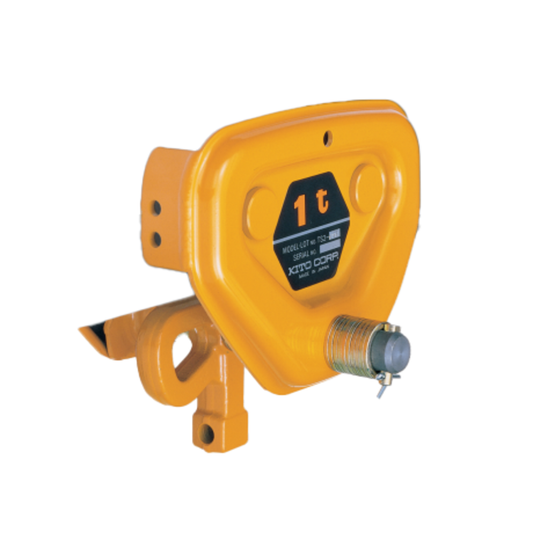
CHARIOT 1 TONNE PLAIN
Part #tsp2010
In Stock
Prix habituel $590.92 CADPrix habituelPrix unitaire par -
Fournisseur :Herc
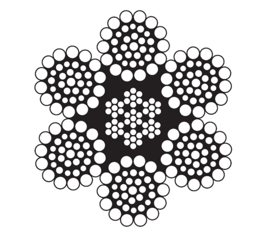
CÂBLE MÉTALLIQUE 1-1/2 6X36 IWRC RRL EIPS GALV
Part #wr24636wc12g17dryx
In Stock
Contact for Price

 In Stock